This project focused on the design and building of an Active DI Box. This blog covers the design of a circuit with a Jack input, an XLR output that receives 48V phantom power and the design of the PCB.
Firstly,
the way the DI Box is powered is via phantom power which is delivered through 2
outputs of the circuit. Phantom power in this case is a DC voltage that is
applied at the output of the circuit in order to power it up. At the same time,
the output of the circuit can still be decoded as 6.8 kΩ resistors sit at the
other end of the cable (at the mixing desk) and connects to the output of the
DI Box in order to see the incoming waveforms.
Secondly,
the project specifications are the input levels: from microphone level up to
line level – that is a maximum of 1V and the source impedance has to be 100
kΩ.
Thirdly,
the final output should be balanced and the circuit has to be suitably enclosed.
With that in mind, the available circuit has been stated below.
 |
| Active DI Box Circuit |
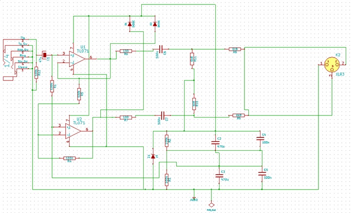 |
| Schematic of an Active DI Box |
The PCB has been designed using existing libraries for KiCad that reflects the component sizes more accurately. The report shows both the schematics and the board.
 |
| PCB Design of an Active DI Box Circuit |
 |
| PCB Testing |
Here is the AC analysis result of the PCB testing from 20Hz to 20kHz:
 |
| Result of the Circuit |
The difference between the input and the output was approximately 6dB because of the pseudo-balanced output.
 |
| Overall Product |
 |
| Overall Product |
 |
| Overall Product |